4 Anatomy of an aircraft
There exists a wide variety of air vehicles that can be grouped in broad categories. The International Civil Aviation Organization (ICAO) classifies “aircraft according to specified characteristics”. The aircraft categorisation has relevance for the flight training and associated licensing, but also for the certification and operation of the aircraft in terms of equipment, operating capabilities and limits, and access to airspace. Aircraft can be broadly categorized into lighter-than-air and heavier-than-air vehicles.
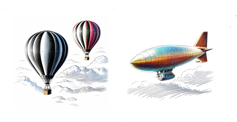
Lighter-than-air aircraft include balloons and airships that achieve flight primarily through buoyancy, using gases like helium or hot air that are less dense than the surrounding atmosphere. These aircraft displace a volume of air greater than their own weight, creating lift without requiring forward motion or wing surfaces. While offering advantages such as low energy consumption, extended flight endurance, and near-silent operation, they typically have limited speed capabilities and are more susceptible to weather conditions compared to their heavier-than-air counterparts. Modern applications range from recreational hot air ballooning to advanced airships designed for surveillance, tourism, and cargo transport in remote areas.
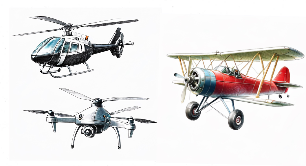
Heavier-than-air aircraft consist mostly of aeroplanes, i.e., engine-driven, fixed-wing aircraft that achieve flight by the reaction of the air flowing around the wing and creating lift. These aircraft generate either aerodynamic forces (for fixed-wing aircraft and rotorcraft) or direct engine thrust (for rockets) to counteract gravity. Unlike lighter-than-air vehicles, heavier-than-air aircraft require forward motion or powered lift to generate sufficient upward force. Heavier-than-air aircraf encompass a wide range of vehicle types including commercial airliners, military jets, helicopters, gliders, and modern unmanned aerial vehicles (UAVs). The category can be further subdivided based on wing configuration, propulsion system, and intended use, with each design optimized for specific performance characteristics such as speed, range, payload capacity, or maneuverability.
When speaking about aircraft categories, often the terms (aircraft) class and (aircraft) type crop up. An aircraft class is a sub-division within a category with a focus on design and performance. For example, single-engine and multi-engine piston engine aircraft. Aircraft type refers to the specific model of an aircraft, such as Boeing 737 or Airbus A320.
In this chapter we focus on conventional airplanes, i.e., powered heavier-than-air aircraft.
4.1 Structure of an aircraft
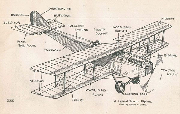
Aircraft consist of several key components that work together to enable flight. These can be broadly categorized into structural components and propulsion systems.
The primary structural components include:
- The fuselage, which houses the cockpit, passengers, and cargo;
- Wings that generate lift;
- Empennage (i.e., the tail section) for stability and control;
- Landing gear for ground operations
The propulsion system provides the necessary thrust for flight through various types of engines.
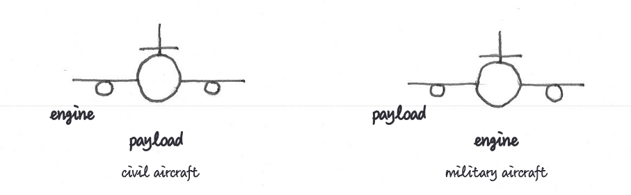
Civil and military aircraft share these basic components but differ significantly in their design priorities. Civil aircraft are optimized for passenger comfort, fuel efficiency, and commercial viability, typically using turbofan engines for economical operation and carrying passengers or cargo as payload.
Military aircraft, conversely, are designed for specific mission requirements such as combat, surveillance, or transport, often featuring more powerful engines like turbojets or afterburning turbofans for greater speed and maneuverability. Their payload usually consists of weapons systems, specialized equipment, or troops rather than commercial passengers. Aircraft consist of several key components that work together to enable flight.
The fuselage is the main body structure of an aircraft that houses the cockpit, passenger cabin, and cargo compartments. It serves as the central framework to which other major components such as wings, empennage, and landing gear are attached. Fuselages are designed to withstand various aerodynamic forces while maintaining structural integrity during flight operations. The cross-sectional shape is typically circular or oval to efficiently handle pressurization loads at altitude, though military aircraft may feature more complex shapes optimized for specific mission requirements. Modern commercial aircraft fuselages are primarily constructed from aluminum alloys or increasingly from composite materials like carbon fiber reinforced polymers (CFRP), which offer improved strength-to-weight ratios and corrosion resistance. The fuselage design must balance multiple factors including aerodynamic efficiency, structural strength, weight considerations, and internal space utilization.
The wings are the primary surfaces that generate lift during flight. They are airfoil-shaped appendages extending from the sides of the fuselage, designed to create pressure differentials as air flows around them. Wings vary in design based on aircraft type and purpose, from the straight wings common on small aircraft to swept wings on commercial jets and delta wings on supersonic aircraft.
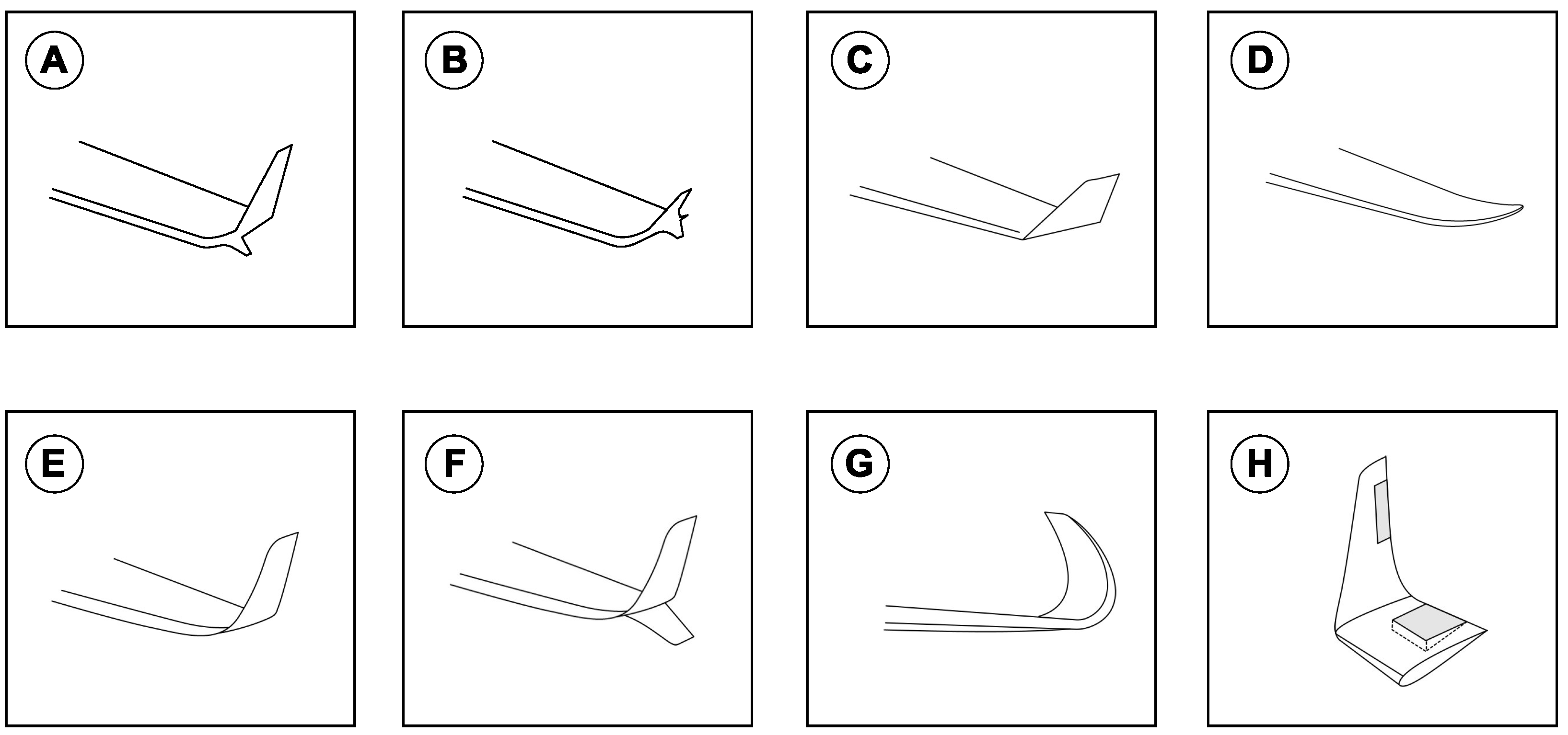
Wing components include ailerons for roll control, flaps and slats to modify lift characteristics during takeoff and landing, and spoilers (or airbrakes) to reduce lift and increase drag when needed1. Modern wings also often feature winglets at their tips to reduce drag-inducing vortices and improve fuel efficiency. Wing construction typically uses aluminum alloys, though composite materials are increasingly common in newer aircraft designs for their superior strength-to-weight ratio and resistance to fatigue.
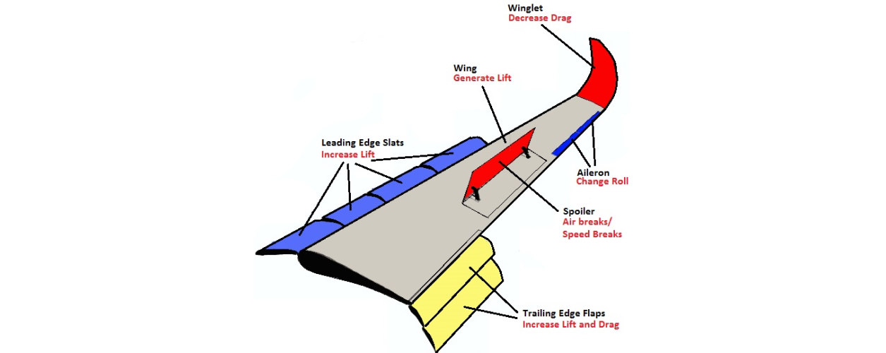
Winglets are a familiar feature on the wingtips of modern commercial aircraft, playing a critical role in improving aerodynamic efficiency. These upward-swept extensions help reduce drag by weakening the wingtip vortices—spiraling air currents caused by pressure differences above and below the wing. By acting as barriers to this turbulent airflow, winglets cut fuel consumption, increase cruising range, and ultimately reduce operational costs.
Since their debut on the Boeing 747-400 in 1988, winglets have become standard on most new-generation airliners. Several types are now in common use, including:
- whitcomb winglets;
- tip fence;
- canted winglets (Boeing 747-400, Airbus A330 and A340);
- raked wingtips (Boeing 787 Dreamliner);
- blended winglets (Boeing 737 and 757);
- blended split winglets;
- sharklets (Airbus A320neo and A350);
- active winglets.
As technology advances, winglet designs continue to evolve, enabling airlines to retrofit older fleets and push fuel efficiency even further.
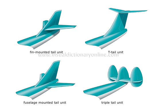
- The tail section (empennage) consists of the horizontal and vertical stabilizers that provide stability and control during flight. The horizontal stabilizer controls pitch through movable elevators, allowing the aircraft to climb or descend. The vertical stabilizer (fin) includes the rudder, which enables yaw control for turning left or right. Together, these components ensure the aircraft maintains directional stability while allowing controlled maneuvers. Modern empennage designs use aluminum alloys or composite materials and may feature various configurations including T-tails, V-tails, or conventional arrangements depending on the aircraft’s purpose and performance requirements.
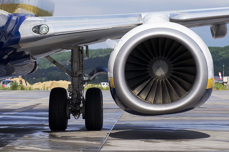
Engines are the power plants that provide thrust for aircraft movement. Modern aircraft use various engine types including piston engines (common in small aircraft), turboprops (combining a gas turbine with a propeller for regional aircraft), turbofans (used in most commercial airliners for their efficiency at high speeds), and turbojets (primarily in military applications). Engine selection depends on the aircraft’s intended purpose, with considerations for thrust requirements, fuel efficiency, operating altitude, and speed range. Most commercial aircraft use twin-engine configurations mounted either under the wings or at the rear of the fuselage, while some military aircraft feature embedded engines to reduce radar signature.
The introduction of turbojets and later turbofans revolutionized commercial aviation. The development of jet engines in the mid-20th century enabled aircraft to fly higher, faster, and more efficiently than propeller-driven predecessors. The first commercial jet airliner, the de Havilland Comet, entered service in 1952, followed by more successful designs like the Boeing 707 and Douglas DC-8. Turbofans, which emerged in the 1960s, provided better fuel efficiency and reduced noise compared to pure turbojets, enabling the growth of mass commercial air travel.
Airframe and engine life cycles are largely decoupled in modern aviation. While airframes are typically designed to last 25-30 years, engines have much shorter service intervals. Aircraft engines generally require major overhauls every 10,000-15,000 flight hours, with complete replacement often necessary after 3-5 major maintenance cycles. This decoupling allows airlines to replace or upgrade engines multiple times during an aircraft’s operational lifetime.
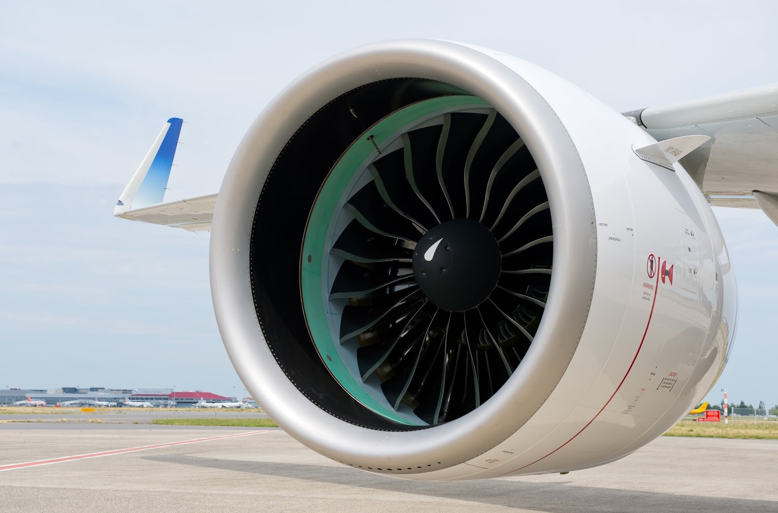
High bypass ratio engines vary significantly in size, with the largest examples being truly massive. For perspective, the GE90-115B engine used on the Boeing 777-300ER has a fan diameter of 3.25 meters and can produce up to 115,000 pounds of thrust. The Rolls-Royce Trent XWB engines powering the Airbus A350 have a fan diameter of about 3 meters (118 inches). For comparison, the entire fuselage diameter of a Boeing 737 narrow-body aircraft could fit inside the intake of these larger engines.
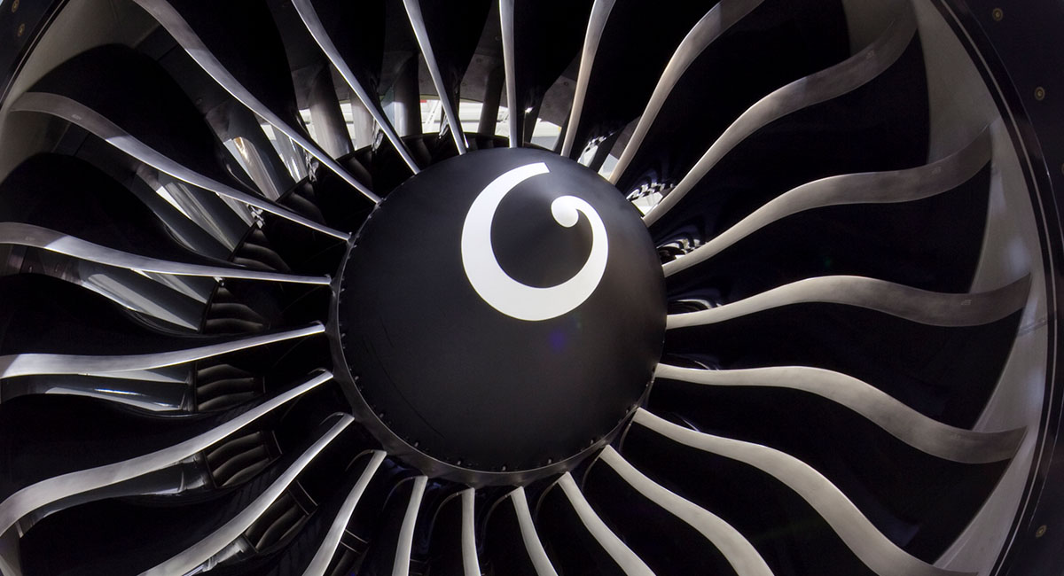
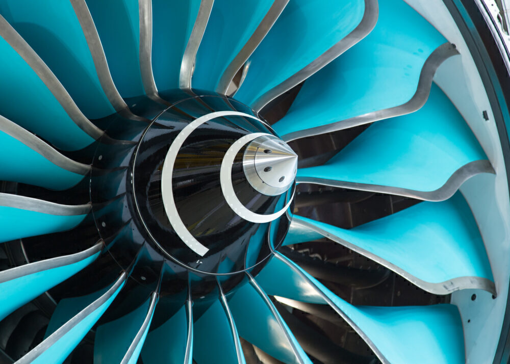
NoteSpinner spiralsMany aircraft engines feature distinctive spiral patterns painted on their spinners (the conical cover over the hub of the propeller). These spirals serve as a visual safety feature: when the propeller is spinning, the spiral creates a visual pattern that reminds ground personnel to keep clear.
Some patterns are distinctive marks of a manufacturer, such as the “G-swirl” for General Electric, the long spiral for Rolls-Royce, or the Pratt & Whitney’s apostrophe.
 Note
NoteMost commercial aircraft use a bleed air system, which extracts compressed air from the engines to power various aircraft systems including cabin pressurization, air conditioning, and anti-icing. This high-temperature, high-pressure air is “bled” from the compressor stages of the engine before fuel is added. The Boeing 787 Dreamliner, however, introduced a significant innovation by implementing a “bleed-less” electrical architecture. Unlike conventional aircraft, the Dreamliner uses electrical compressors and pumps powered by generators on the engines instead of the traditional bleed air system.
This approach allows smaller, more efficient engines. A significant visual mark for the Dreamliner is a distinctive air intake on the fuselage that supplies air to the electrical compressors, replacing the traditional bleed air ports on the engines found on conventional aircraft.

https://www.jetphotos.com/photo/11688506 Aircraft fuel is primarily stored in the wings, utilizing the space between the front and rear wing spars to form integral fuel tanks. This location offers several advantages: it keeps the heavy fuel mass close to the aircraft’s center of gravity, utilizes otherwise empty space, and as fuel is consumed, the reduced wing loading helps decrease structural stress. Modern commercial aircraft like the Boeing 747 and Airbus A380 may also incorporate additional fuel tanks in the horizontal stabilizer or dedicated sections of the fuselage for extended range operations. Most aircraft feature multiple, isolated fuel tanks with cross-feed systems to maintain balance and provide redundancy in case of pump failure or fuel system damage.
The Auxiliary power unit (APU) is a small turbine engine typically located in the tail section of an aircraft that provides power independently of the main engines. It powers systems on the ground when main engines are off, provides bleed air for starting the main engines, and serves as a backup power source during flight. APUs allow aircraft to operate at airports without requiring external power or pneumatic sources, enabling air conditioning, lighting, and instrument operation even when the aircraft is parked with main engines shut down.
NoteMany airports restrict APU usage due to environmental concerns, particularly noise and air pollution. These restrictions may limit APU operating times, especially during night hours or at gate positions where fixed ground power and pre-conditioned air are available. Major European airports such as Zurich, Frankfurt, and London Heathrow have implemented strict APU operating limitations to reduce emissions and noise in their sustainability efforts.
The landing gear (undercarriage) is the structural component that supports the aircraft when on the ground during taxiing, takeoff, and landing. It typically consists of wheels, shock absorbers, and retraction mechanisms (in most modern aircraft). The three main configurations are: tricycle (with a nose wheel and two main wheels), conventional/“taildragger” (with a tail wheel and two main wheels), and tandem (with wheels arranged along the centerline). Modern commercial aircraft use complex multi-wheel bogie systems to distribute weight across multiple tires. Landing gear must absorb landing impact forces, provide stability during ground operations, and in retractable systems, stow compactly during flight to reduce aerodynamic drag. The system also incorporates brakes for deceleration after landing and during taxi operations, as well as a steering mechanism (typically on the nose wheel) for directional control on the ground.
NotePushback operations are a standard procedure at airports where aircraft are pushed backward from their gates by specialized tow vehicles before taxiing to the runway. This is necessary because most commercial aircraft cannot reverse under their own power. The pushback tug connects to the aircraft’s nose landing gear via a towbar or towbarless system, and is controlled by ground crew in communication with the cockpit.
Single engine taxiing is a fuel conservation practice where aircraft taxi using only one engine instead of all engines, reducing fuel consumption by 20-40% during ground operations. While widely adopted, this practice requires consideration of factors like aircraft weight and weather conditions. More recently, electric taxiing systems have been developed, allowing aircraft to move on the ground using electric motors installed in the landing gear or using external tugs, further reducing emissions and noise at airports.
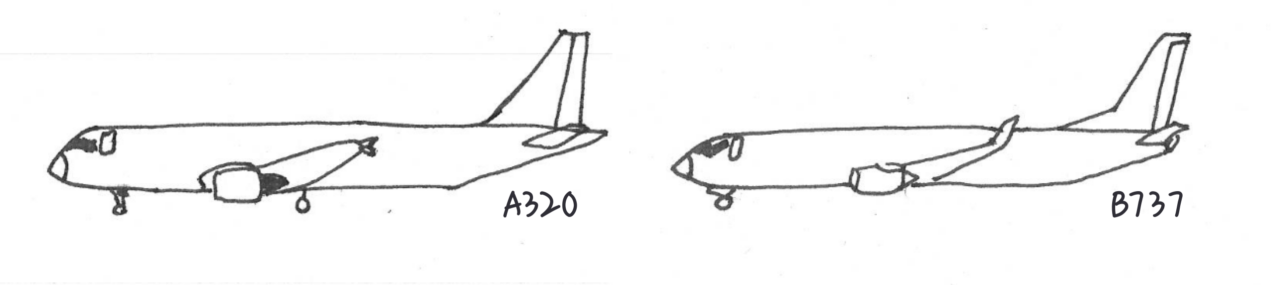
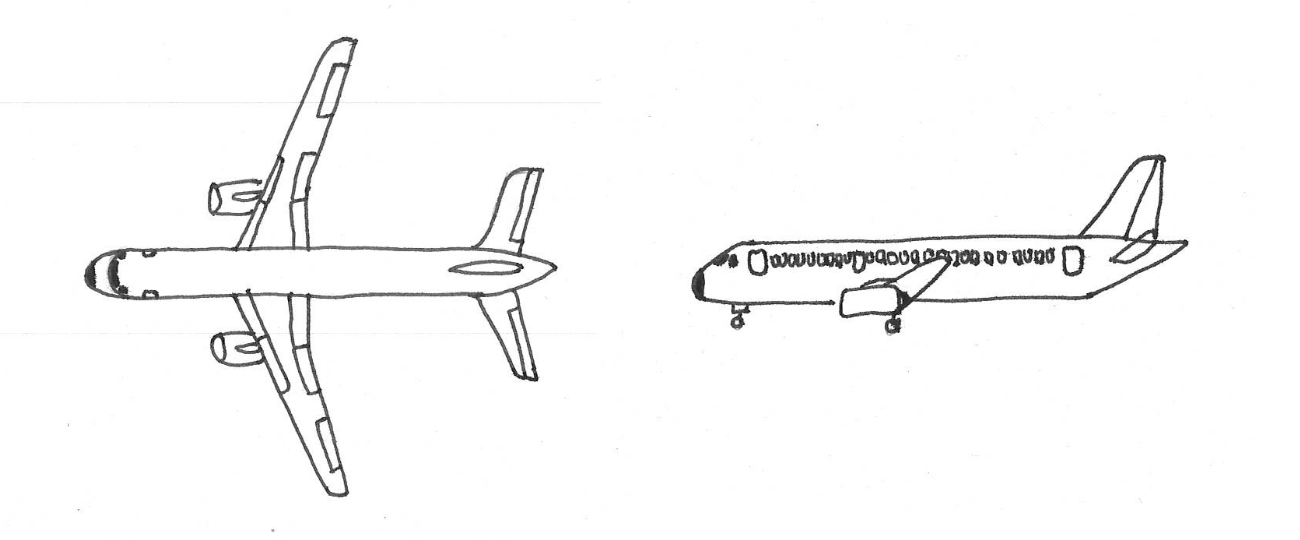
The A320 and 737 have several distinctive differences despite being similar-sized narrow-body aircraft:
- Nose design: The A320 has a more rounded nose cone compared to the 737’s pointed profile
- Landing gear height: The 737 sits notably lower to the ground than the A320
- Engine mounting: On the A320, engines are attached with pylons that provide more clearance below them, while the 737’s engines are mounted closer to the wing underside
- Tail section: The A320 features a more vertical stabilizer compared to the 737’s slightly swept design
- Winglet design
The 737’s low ground clearance is particularly noteworthy: its engine nacelles have a distinctive flattened bottom section to maintain minimum required ground clearance, as shown below on Figure fig-engine_b737.
4.2 Flight mechanics
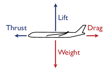
The movement of aircraft is governed by the interplay of four forces determining the trajectory of the aircraft. These forces oppose each other. Conceptually, the flight movement is the result of balancing these forces with the aforementioned controls and available propelling power.
Lift is generated as the result of the airspeed and the interaction of (predominantly) the wings with the passing air. Thus, thrust and angle of attack (aircraft attitude) are the main drivers of lift.
Weight is the force created by the mass of all components and the payload on board of an aircraft, e.g. including the passengers, cargo, fuel.
Thrust is generated by the aircraft power plant system. It acts in the forward direction.
Drag acts rearward and opposite to the direction of flight. Drag is composed of two principal components: the air drag is produced by the shape of the aircraft and the induced drag is the by-product of the lift force.
Aircraft movement is therefore the resultant force of these four principle forces. For example, for straight and level flight, i.e. the aircraft is neither climbing nor descending and neither accelerating or decelerating. Accordingly, all four forces are in balance acting in opposite directions. The lift vector is matching the weight vector, and thrust matches drag.
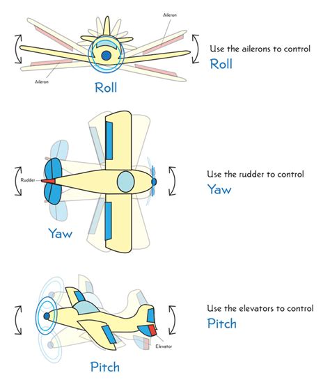
For the directional control of aircraft, movable parts allow the pilot/aircrew to steer the aircraft and change its direction of flight and attitude using aerodynamical forces.
- up-down movement control - “pitch”: elevators. Elevators are (typically) attached to the horizontal stabiliser
- left-right turn control - “yaw”: rudder. Surface attached to the vertical stabiliser
- longitudinal “roll”: ailerons typically attached to the trailing edge of wings
When the pilot pulls back on the control stick, the elevators deflect upward, increasing the angle of attack of the horizontal stabilizer. This creates a downward force on the tail, which pitches the aircraft’s nose upward. This rotation occurs around the aircraft’s center of gravity. If the center of gravity is forward of the center of lift (located on the wings), the aircraft exhibits positive stability - when disturbed from equilibrium, aerodynamic forces naturally restore it to a stable position. Conversely, if the center of gravity is behind the center of lift, the aircraft becomes inherently unstable - any pitch deviation tends to amplify rather than correct itself. Some modern aircraft like the Airbus A380 are deliberately designed with reduced natural stability to enhance maneuverability and efficiency. In these cases, sophisticated fly-by-wire systems with computer-controlled feedback continuously make minor adjustments to maintain stable flight characteristics that would be impossible for a pilot to achieve manually.
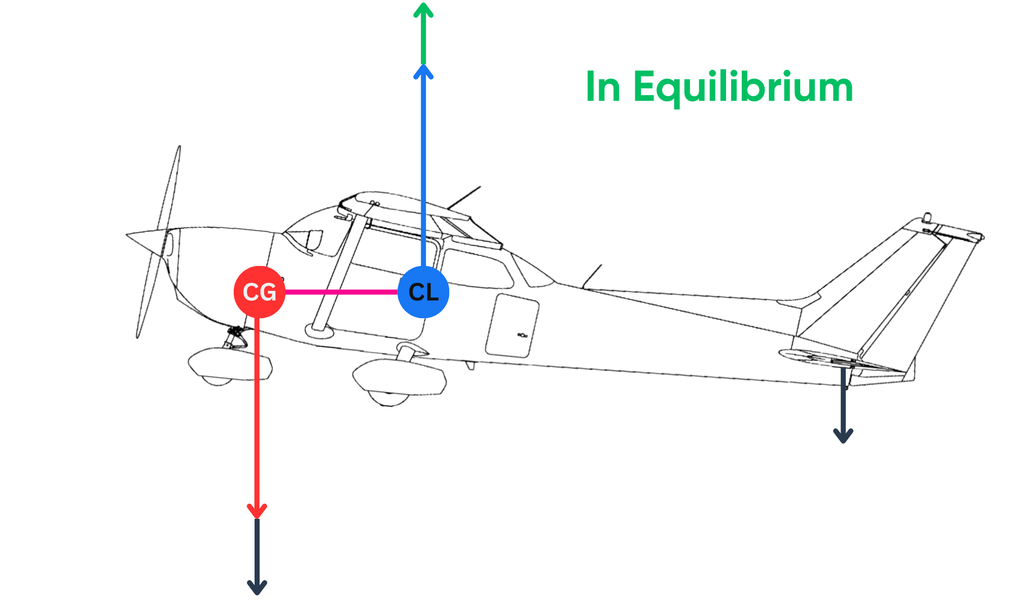
Centering of an aircraft is critical for flight stability and safety. The center of gravity must fall within specific limits defined by the manufacturer. If the center of gravity is too far forward, the aircraft becomes nose-heavy, potentially requiring excessive elevator force to maintain level flight. Conversely, if the center of gravity is too far aft, the aircraft becomes tail-heavy and potentially unstable. Aircraft loading systems carefully calculate the weight distribution of passengers, cargo, and fuel to ensure the center of gravity remains within acceptable limits throughout the flight. For larger commercial aircraft, fuel can sometimes be transferred between tanks during flight to optimize the center of gravity position for best performance and fuel efficiency.
Banking turns demonstrate the strong correlation between yaw and roll in aircraft control. When an aircraft executes a turn, both roll and yaw movements must be coordinated. The pilot initiates a turn by using ailerons to roll the aircraft toward the desired direction, banking the wings. This banking causes the lift vector to tilt, creating a horizontal component that pulls the aircraft into the turn. When an aircraft banks to the left, the right wing creates more lift than the left wing, creating additional induced drag on the right side: the aircraft tends to yaw in the opposite direction of the roll angle. Without proper rudder input, the aircraft would slip or skid through the turn, resulting in inefficient flight and passenger discomfort. This coordination of roll and yaw controls is fundamental to executing smooth, balanced turns and is one of the primary skills mastered during pilot training. Gliders often use a red yarn or string mounted on the canopy as a visual yaw indicator to help pilots maintain coordinated flight during turns.
Speeds
4.4 Aircraft systems
4.4.1 Identification
Transponder
4.4.2 Flight control systems
Modern aircraft are equipped with sophisticated avionics (aviation electronics) that assist pilots in navigation, communication, and overall aircraft management.
Flight Management System (FMS) is the central computer system that integrates navigation, performance, and engine control functions. It allows pilots to program the entire flight route before takeoff, monitors fuel consumption, calculates optimal speeds and altitudes, and interfaces with autopilot systems. The FMS typically includes a Control Display Unit (CDU) with a small screen and keyboard in the cockpit through which pilots interact with the system. Modern commercial aircraft rely heavily on FMS for efficient operation, especially during long flights where fuel optimization is critical.
Autopilot systems automatically control flight without constant pilot intervention, reducing workload during long flights. Basic autopilots maintain altitude and heading, while advanced systems can execute complex maneuvers including takeoffs and landings. These systems work by receiving input from various sensors and the FMS, then manipulating flight controls to maintain desired parameters. Most commercial flights operate with autopilot engaged for the majority of the flight, with pilots monitoring systems and intervening when necessary.
4.4.3 Safety Systems
Weather Radar allows pilots to detect and avoid severe weather conditions by displaying precipitation intensity on cockpit screens. These systems are essential for identifying thunderstorms and turbulence that could pose hazards to flight safety.
Enhanced Ground Proximity Warning System (EGPWS) uses radar altimeter data and a terrain database to provide alerts when aircraft approach terrain dangerously. This system has dramatically reduced controlled flight into terrain (CFIT) accidents by giving pilots clear “pull up” warnings when necessary.
Traffic Alert and Collision Avoidance System (TCAS) / ACAS In order to ensure the safe travel of aircraft a series of safety systems were developed. Airborne Collision Avoidance System (ACAS) is a generic term to describe systems that track the surrounding air traffic on the basis of their tansponders. Dependent on the determined distance and relative range rate and approach speed, a potential risk of collision can be detected.
Traffic alert and Collision Avoidance System (TCAS) is an implementation of the ICAO ACAS standard. To our knowledge, there are no other implementation of ACAS. TCAS II is mandated in Europe since the year 2000 and addresses changes to the logic of the detection and resolution logic. We consider therefore both terms as interchangable.
ACAS/TCAS issue two types of alerts:
- Traffic Advisory (TA) to support the pilot/aircrew to visually identify a potential conflicting flight
- Resolution Advisory (RA) is an avoidance maneuver. If both aircraft are equipped with an ACAS, the avoidance maneuvers are coordinated between the ACAS units via datalink.
4.4.4 Environmental Control Systems
Environmental Control System (ECS) manages cabin pressurization, temperature, and air quality. At cruising altitudes (typically 30,000-40,000 feet), the outside air is too thin and cold for humans. The ECS compresses this air, heats it, and circulates it throughout the cabin to maintain a comfortable environment equivalent to approximately 6,000-8,000 feet altitude. This system also filters the air, with most modern aircraft completely refreshing cabin air every 2-3 minutes through a combination of recirculated and fresh air.
Anti-icing systems prevent ice buildup on critical surfaces like wings, tail, engine inlets, and pitot tubes (airspeed sensors). These systems typically use heated air from the engines or electrical heating elements. Ice accumulation can drastically alter the aerodynamic properties of wings and control surfaces, potentially leading to dangerous flight conditions.
Glossary
- ACAS
- Airborne Collision Avoidance System
- FMS
- Flight Management System
- ICAO
- International Civil Aviation Organization
- NAVAID
- NAVigational AID
- RA
- Resolution Advisory
- TA
- Traffic Advisory
- TACAN
- TactiCal Air Navigation system
- TCAS
- Traffic alert and Collision Avoidance System
- VOR
- Very High Frequency Omnidirectional Range Station
Some aircraft, such as the Airbus A300, also use spoilers for roll control in addition to or instead of traditional ailerons, particularly at high speeds where aileron effectiveness may be reduced.↩︎